 The
figure to the right shows a similar scheme that is currently in use – one in which a
capacitor is placed across a laser diode. In this application, typical
capacitor values range from several hundred nanofarad to several
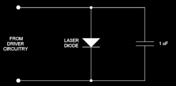
microfarad. The
figure to the right shows a similar scheme that is currently in use – one in which a
capacitor is placed across a laser diode. In this application, typical
capacitor values range from several hundred nanofarad to several
microfarad.
At first glance, a 1-microfarad capacitor would
appear to be sufficient to limit a 15,000-volt ESD event from exceeding
the maximum reverse bias voltage of 2.0 volts and similar forward-bias
limits. However, in real life, there are no capacitors known to exist that
have purely capacitive characteristics.
All known real-world electrical components have
parasitic properties. Small capacitors can be modeled by the nominal
capacitance in series with a parasitic resistance in series with a
parasitic inductance.
As discussed, an ESD event occurs within the range
of a below one nanosecond up to a few tens of nanoseconds; thus, the
frequency-domain equivalent of this is around 20 MHz up to 1 GHz.
Therefore, the impedance of the capacitor would need to be less than 44
milliohms between around 20 MHz and 1 GHz in order to be effective at
protecting the laser diode.
Common 1-microfarad electrolytic capacitors have an
equivalent series resistance of 1 ohm, and an equivalent series inductance
of around 15 nanohenry. This combination clearly gives an impedance
greater than 44 milliohms. And although the best 1-microfarad tantalum
capacitors have an equivalent series resistance that can approach 50
milliohms, their equivalent series inductance is usually at least 1
nanohenry, which gives an impedance over 6 ohms at 1 GHz. It is not known
whether a capacitor actually exists whose impedance is 44 milliohms within
the frequency range of interest.
However, even if a perfect capacitor were used that
would be effective at protecting the laser diode against ESD, such a
capacitance makes direct modulation of a laser diode increasingly
difficult, especially at high modulation frequencies. Thus, there are
clear drawbacks to this simple capacitive approach.
Moreover, other studies have shown how ESD can
destroy ceramic capacitors. Such a study can be found here:
http://www.ce-mag.com/archive/01/Spring/Lee.html
|
