ESD polarity terminology used on this web site
The term “positive-ESD” is used to mean electrostatic discharge (ESD) whose voltage polarity would tend to forward-bias a laser diode. “Negative-ESD,” means ESD whose voltage polarity would tend to reverse-bias a laser diode.
|
Review of ESD approaches |
||||
| START | PREV | CURRENT/END | ||
|
Introduction << |
||||
Review of ESD approaches
LASORB’s improved approach to ESD protection
LASORB is an electronic component that is designed specifically to protect laser diodes from ESD and power surges. LASORB can also be used to protect other types of optoelectronic devices such as Superluminescent Diodes, LEDs and Photodiodes.
LASORB overcomes the problems of previously known ESD protection schemes by preventing reverse-bias of the laser diode. It also prevents ESD or other power-related faults from exceeding (and in many cases, even reaching) the maximum forward-bias voltage of the laser diode. LASORB is able to do this while not adding significant resistance or capacitance to the laser diode, thereby not complicating the task of driving the laser diode.
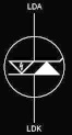
The LASORB circuit symbol
LASORB is connected directly across the terminals of a laser diode, with the LDA terminal of LASORB connected to the Laser Diode Anode, and the LDK terminal connected to the Laser Diode Cathode. As shown in the LASORB symbol below, the LASORB can be thought of as two separate parts. Each part will be described separately to aid in a complete understanding of how it works.
Negative ESD (and reverse bias) protection
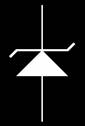 LASORB symbol (right side)On the right hand side of the LASORB symbol, you can see the symbol for what appears to be a Zener diode.
This portion of LASORB prevents negative-ESD – that is, ESD whose polarity would tend to reverse bias the laser diode. This portion of the LASORB is a made of very fast acting PN junction. The forward voltage of this junction will not exceed 2 volts, even during 50-amp ESD events.
The maximum peak inverse voltage of LASORB varies as a function of the part number, and parts can be customized to operate up to 20 volts. Above the maximum peak inverse voltage, an “avalanche” condition exists, and, although not designed to be used this way, no damage will come to the LASORB as a result of operating it at the avalanche voltage. Since LASORB can withstand operation at the avalanche voltage, we chose to indicate this portion of LASORB using the Zener diode symbol.
ESD/power surge protection
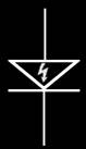 LASORB symbol (left side)On the left hand side of the LASORB symbol, you will see the symbol for a new kind of diode.
This portion of LASORB is a diode that is triggered by ESD or power surges. When the voltage at the LDA terminal of LASORB rises at a high rate when compared to the LDK terminal, the LASORB activates this special diode, which conducts current and diverts the ESD through the LASORB instead of allowing it to pass through the laser diode. When activated, the voltage across this portion of LASORB will not exceed the nominal operating voltage of the laser diode, even during 50 amp ESD surges.
During normal laser operation, the voltage across the laser diode normally does not change much, even during modulation. Because of this, LASORB will remain inactive, presenting only a slight resistive and capacitive load on the driver. But if an ESD event occurs while the laser diode is operational, this too will be detected, and the special diode will once again be triggered, diverting ESD through LASORB instead of through the laser diode. The theoretical reaction time of LASORB is between 200 and 800 picoseconds, so it is fast enough to react to nanosecond-level ESD events.
Datasheets
For more detailed information, go to the Datasheets page. You can download PDF datasheets on our various LASORB formulations, optimized for particular types of laser diodes.
